Blog

Budget-Friendly Tips to Boost Heat Treat Furnace Efficiency – Part 1
Many manufacturers are feeling immense pressure from rising operating expenses today. Increased costs for raw materials, energy, and maintenance for aging equipment paired with other global factors impact operations. Supply chain delays and labor shortages mean manufacturers need help getting the most out of all their existing equipment. At the same time, manufacturers must also comply with a variety of changing environmental and safety regulations as well. At George T. Hall (GTH), we have seen that this set of challenges is especially impacting manufacturers who rely on energy-intensive heat treating as part of their process.
Replacing older, inefficient, yet functioning industrial furnaces are usually not in the budget for most manufacturers. We, at GTH, have a team of combustion and instrumentation specialists that focus on optimizing productivity, energy usage, and profitability by tweaking sources of minor inefficiencies in existing furnaces. In this blog series, we will review our team’s top four tips for low-cost ways to bring more uniformity and reliability to your heat process, improving productivity and profitability, while also staying in compliance with evolving regulatory requirements where applicable.
Tip 1: Determine if Your Furnace Has an Optimal Fuel-to-Air Ratio
Throughout our 50 years of working with combustion control systems, we frequently see that there are multiple sources skewing fuel-to-air ratio in many industrial furnaces. While our team of combustion specialist are available to visit your facility to evaluate your burner air delivery systems and provide an in-depth report with recommendations on how to reduce downtime and improve burner operation, we also want to share a few of the most common sources of inefficiencies we see.
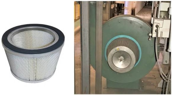
For starters, a very common, and easy-to-fix, source of inefficiency we typically see is that the combustion blower filter is very dirty or clogged. While most people are aware their home heating and cooling system has a filter that needs to be replaced regularly for efficient operations, in the industrial workplace, the combustion blower’s filter is often forgotten about. This is problematic because a dirty combustion blower filter can cause the entire furnace to heat inconsistently and inefficiently – using more energy, producing more emissions, and impacting profitability (Figure 1).

Figure 1. A clean blower filter (left) and a dirty blower filter (right) in operation.
Therefore, routinely checking and cleaning this filter should be a priority item on your preventative maintenance list. But who’s responsibility is that? To avoid this internal debate, one solution is to systemize this task by installing a pressure differential switch from the blower inlet to the blower outlet that provides a notification, or “dirty filter alarm”, when a drop in air volume occurs that impacts burner operations.
To create the setpoint for your “dirty filter alarm,” we recommend installing a clean filter and operating your burner system at maximum input. Next, using a piece of paper, slowly restrict the airflow through the filter until you see a degradation in burner performance. Just prior to that point of degradation in burner performance, set your pressure switch to initiate the “dirty filter alarm.” When this alarm is triggered, it will signal your maintenance team to perform the required filter cleaning or replacement keeping your burner system operating as designed.
Another frequent source of inefficiency we run into stems from the use of traditional butterfly control valves connected to actuators via mechanical linkage. By replacing these older valves with newer direct-coupled adjustable port valves and eliminating the mechanical linkage you can remove the hysteresis component from the control equation, resulting in increased repeatability. The adjustable port valve will also allow for linearized flow and easier tuning.
Additionally, many burner systems today are still using back loaded gas regulators, zero governors, bleed blocks, and ratio regulators. These systems can also be cost-effectively upgraded to use electronic parallel positioning or metered control schemes, which will provide better fuel-to-air ratio control and reduce operational maintenance costs. Since making these changes may require a little more control system knowledge, we can provide technicians to work with your staff to make any of these changes.
Tip 2: Create Temperature Control Uniformity that also Complies with Newer Regulations
Another easy-to-fix source of inefficiency in many heat treat systems is the actual position of the control thermocouple in the furnace, which is the key for performing temperature control. When a temperature uniformity survey (TUS) reveals the temperature is not correct at the load, which frequently happens, rather than address this problem directly many technicians will bias the temperature controller to create an offset and get uniformity at the load. But doing this does not address the root of the problem, which is that the thermocouple location is improper.
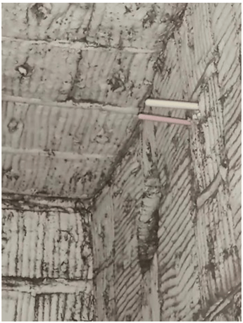
To determining the best location for the thermocouple, we recommend inserting two or three test thermocouples into the furnace, connecting the thermocouples to a temperature recorder, and running another TUS. Then, monitor the test thermocouples to determine which sensor best represents your target setpoint. Next, remove any bias from the temperature controller and temporarily connect the thermocouple that displays the closest temperature to the target setpoint. Then, run another TUS using this thermocouple as the control reference for your setpoint. In most cases, when you find the correct thermocouple location, the need to introduce an offset or bias will be minimal and/or eliminated and you will now have repeatable uniformity in your furnace, which will lead to more efficiency (Figure 2).

Figure 2. Thermocouples installed in the furnace sidewall.
If this process seems daunting, GTH can help. Our team of furnace control specialist have decades of experience working with customers to analyze TUS’s and can make recommendations for sensor placement. We can additionally identify if the issue goes beyond sensor placement and another service, such as adjusting burner tuning or load placement, is needed.
Related to this, heat treater furnaces must meet critical temperature control, documentation, and compliance requirements. Likewise, it is important to know that in June 2020, a new requirement outlined in the AMS2750F specification related to the readability of furnace temperature recording field instruments went into effect. The previous readability requirement of 1.0°F was changed to 0.1°F and a digital reading must be available. This meant all chart recorders needed to be upgraded to video recorders. If you have not yet been able to meet this requirement, as of June 2022, AMS2750G part 3.2.3.2.1 states; Digital recording instruments that only read in whole numbers may be used for 1 year after the release of AMS2750 Rev G and shall have maximum calibration accuracy of ±2 °F or ±1 °C or ±0.2% of the temperature reading rounded inward towards the smaller whole number. GTH technicians can work with you to seamlessly upgrade your facility-wide paper chart recorders to AMS2750G-compliant graphic recorders.
In the next part of this series, we will explore tips for pressure control tuning and upgrading outdated sensor technology. In the meantime, you can learn more about our experience working with heat treat furnaces and other industrial applications.
RELATED POSTS
Fireye introduces the new BurnerLogiX Flame Safeguard with valve proving and low gas pressure...
How has climate change affected us locally?Like all other regions of the globe California has seen the...


